|
 U
U se se
This pump is a single-stage single-suction anticorrosive centrifugal
pump sucking from axial direction. The pump body liner, pump cover
liner, piper liner and bearing bush are all produced from fluon
by one-time mould pressing, sintering method. The pump axis is made
from 3Cr13 stainless steel and fluon spindle sleeve outside.
Fluon is one of the excellent anticorrosion material. It has very
low coefficient of friction, high self-lubricity and inadhesion,
can be used during the temperature range of -195-250 for long time. It can be used in acid, alkali and salt solution,
strong oxidizer, organic solvents and other media(besides high-temperature
molten alkali metals, element fluorine and chlorine trifluoride).
This pump can be used to transport liquid in the industries of chemical,
petroleum, metallurgy, pharmacy, paper making, dyeing and printing,
war industry, environmental protection, seawater desalination, etc.
Its anticorrosive property is highly better than other pumps made
from stainless steel and non-metal materials such as glass, ceramic,
graphite, silicon iron, other fluoro plastic, glass fibre reinforced
plastic and F46, etc.
for long time. It can be used in acid, alkali and salt solution,
strong oxidizer, organic solvents and other media(besides high-temperature
molten alkali metals, element fluorine and chlorine trifluoride).
This pump can be used to transport liquid in the industries of chemical,
petroleum, metallurgy, pharmacy, paper making, dyeing and printing,
war industry, environmental protection, seawater desalination, etc.
Its anticorrosive property is highly better than other pumps made
from stainless steel and non-metal materials such as glass, ceramic,
graphite, silicon iron, other fluoro plastic, glass fibre reinforced
plastic and F46, etc.
Characteristics of IHF4 type

1. |
All sections contacting
with liquid are all lined with fluon(PTFE, or F4),
basically, the thickness is at least of 15mm, and the thickest
is up to 35mm. The thickness of metal crust is 10-15mm. It has
higher strength than domestic any other fluoro plastic pump
and its run is safe and reliable. |
| |
2. |
The pump is designed according to the international standard
ISO2858-75, 3661-77, 3069-74 and ISO/DIS5199(equivalent to GB5662-85,
GB5660-85, 5661-85, 5656-85). |
3. |
All the parts are high in mechanical strength
, good in precision. |
4 |
The working efficiency of pump is high. And it
saves recourses. |
5. |
Shaft seal is stable and reliable. |
| |
Assistance impeller, at the back of impeller with
over lift of 50 meters, can reduce the pressure of mechanical
seal cover and improve the reliability of mechanical seal. |
6. |
Convenient to be checked and mended. |
Structure diagram
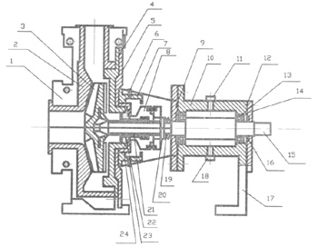
| 1. Pump body |
2. Pump body liner |
3. Impeller |
4. Pump cover liner |
| 5. Pump cover |
6. Feed water tie-in |
7. Water jacket |
8. Dynamic ring |
| 9. Bearing cap |
10. Bearing block |
11. Petrol cup |
12. Tab |
| 13. Bearing |
14. Back bearing cover |
15. Shaft |
16. Oil seal |
| 17. Bear frame |
18. Drain oil |
19. Butterfly spring |
20. Distance ring |
| 21. Stationary seal ring |
22. Axle box |
23. Drainage pipe |
24. Stationary seal ring cover |
|